CONVERTING 4-20mA TO ENGINEERING UNIT
a. Click Select and choose 4-20mA to Value.
b. Insert mili amperes value in tab mA Value.
c. Insert minimum range of the Engineering Unit to the LoRa tab. Insert maximum range of the Engineering Unit to the HiRa tab. LoRA stands for Lower Range. HiRa stands for Higher Range.
d. Select the Mode option. Linear is for linear conversion. Square Root is for square root conversion. The calculate button will be changed based on your choice.
e. The result will be displayed in tab Result (EU) after you click CLICK TO CALCULATE (LNR) for Linear Mode or CLICK TO CALCULATE (SQRT) for Square Root Mode.
CONVERTING ENGINEERING UNIT TO 4-20 mA
a. Click Select and choose Value to 4-20mA.
b. Insert desired value to be converted in tab Desired Val.
c. Insert minimum range of the Engineering Unit to the LoRa tab. Insert maximum range of the Engineering Unit to the HiRa tab. LoRA stands for Lower Range. HiRa stands for Higher Range.
d. Select the Mode option. Linear is for linear conversion. Square Root is for square root conversion. The calculate button will be changed based on your choice.
e. The result will be displayed in tab Result (EU) after you click CLICK TO CALCULATE (LNR) for Linear Mode or CLICK TO CALCULATE (SQRT) for Square Root Mode.
DISCREPANCY CONVERTER FOR ROCKWELL TRUSTED
a. Click Select and choose Discrepancy to Channel (Rockwell Trusted). This function is to identify discrepancy channel by convert it from decimal number to binary.
b. We separate the channel into 3 sections. Channel 1-16, Channel 17-32, and Channel 33-40. This separation is based on Rockwell Trusted itself.
c. Insert the displayed number in Trusted Toolset to Channel Coloumns. Note: the range for Channel 1-16 and Channel 17-32 are 0 to 65535. The range for Channel 33-40 is 0 to 255.
d. Click CALC button which is located beside the channel tab.
e. Instruconverta will locate the discrepancy channel by mark it with red square.
DP FOR LEVEL CALCULATION
b. There are 2 tank types for Calculation. Open/Atmospheric Tank and Closed Tank. For Atmospheric Tank, you can choose Open Tank in Tank Type tab. For Closed Tank, you can choose it in Tank Type tab too.
-Open Tank (Atmospheric Tank)-
c. There are 2 calculation types of Open/Atmospheric Tank. Exact Tapping Point and Below Tapping Point. This option will be shown in Tapping Point tab after you choose the tank type in Tank Type tab.
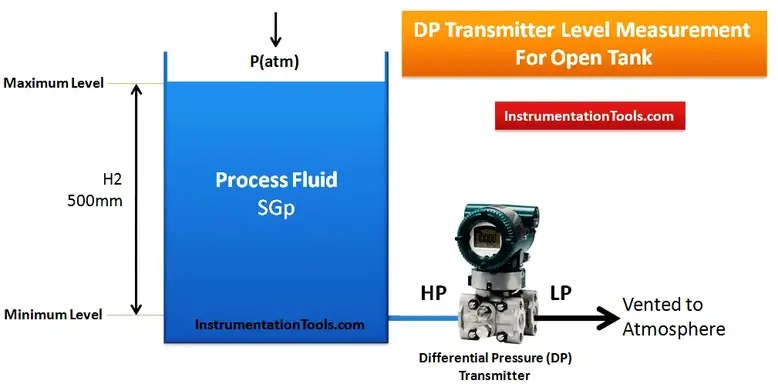
d. If you choose Exact tapping point, you just need to input Specific Gravity number in Specific Gravity (SG) tab and Tank Maximum Level (in mm) in Maximum Level (in mm) tab. After you insert these values, click Calculate and then Instruconverta will calculate it for you.
e. The calculation of Exact Tapping Point in an Open Tank is shown below

Source: https://instrumentationtools.com/open-tank-dp-level-transmitter-calculations/
H2 is a Maximum Level of tank/Maximum level to be measured. LRV (Lower Range Value) always 0 in this type of tank. for URV (Upper Range Value), the formula is H2 multiplied by specific gravity.
f. Another type of tapping point is "below" tapping point. To enter this mode, select Below in Tapping Point tab.
g. After Select Below in Tapping Point tab, Instruconverta shows 3 calculation inputs. Specific Gravity (SG), Maximum Level (in mm), and Lower Tapping Distance (in mm). Lower Tapping Distance is a distance between minimum level of tank to be measured and the DP transmitter itself (H1 in picture below).

Source: https://instrumentationtools.com/open-tank-dp-level-transmitter-calculations/
for Below tapping point, LRV is calculated by multiply H1 to Specific Gravity. URV is calculated by this formula: (H1+H2)*Specific Gravity.
-Closed Tank-
h. There are 2 calculation types of Closed Tank. Dry Calculation and Wet Calculation. This option will be shown in Tapping Point tab after you choose the tank type in Tank Type tab.
i. Dry leg calculation is used when low side of DP transmitter filled with air. If you choose dry leg calculation, you just need to input Specific Gravity number in Specific Gravity (SG) tab, Tank Maximum Level (in mm) in Maximum Level (in mm) tab, and distance between minimum level to DP tapping point in Lower Tapping Distance (in mm) tab. After you insert these values, click Calculate and then Instruconverta will calculate it for you.
j. The Dry Leg Calculation in an Closed Tank is shown below

Source: https://instrumentationtools.com/dp-transmitter-dry-leg-wet-leg-calculations/
the formula for LRV is H2*Specific Gravity - 0.
the formula for HRV is (H2+H1)*Specific Gravity - 0
k. Wet leg calculation is used when low side of DP transmitter filled with other liquid (might be in different SG too). If you choose wet leg calculation, you need to input Specific Gravity number in Specific Gravity (SG) 1 and Specific Gravity (SG) 2 tab. SG 1 is for main level liquid, SG 2 is for low side of DP transmitter liquid. After input SG Values, you need to input Tank Maximum Level (in mm) in Maximum Level (in mm) tab, and distance between minimum level to DP tapping point in Lower Tapping Distance (in mm) tab. After you insert these values, click Calculate and then Instruconverta will calculate it for you.
j. The Wet Leg Calculation in an Closed Tank is shown below

Source: https://instrumentationtools.com/dp-transmitter-dry-leg-wet-leg-calculations/
the formula for LRV is H2*Specific Gravity 1 - (H1+H2)*Specific Gravity 2.
the formula for HRV is (H1+H2)*Specific Gravity 1 - (H1+H2)*Specific Gravity 2